Transfer function of first-order delay system |
|||||||||||
・First-order delay system ・Transfer function ・Bode plot ・secondary delay system ・Bode plot ・Butterworth filter ・Bessel filter ・Transfer function ・Pade approximation |
・ In Japanese
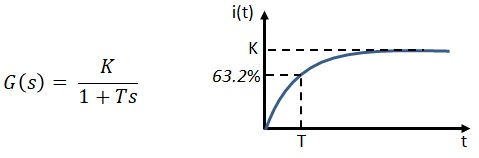
Understand the behavior of an object with a first-order delay transfer function. ■Transfer function of first-order delay system
The differential equation of the RL circuit and the transfer function G (s) of V (t) and i (t) are as follows.
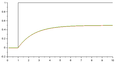
■Confirm the operation of the first-order delay system with Scilab
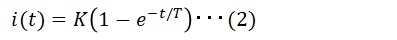
Compare equation (1) with the state of the transfer function. The parameters are as follows. ■Stability of first-order delay system
Since the stability of the system can be known from Eq. (2), it can also be determined from the transfer function obtained by converting Eq. (2). ■Characteristic equation of first-order delay system
I explained that the stability of an object is determined by the value of T.
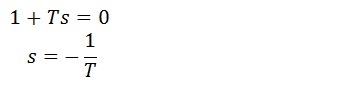
In the case of a transfer function, the following equation with a denominator of 0 is called a characteristic equation, and the stability can be determined by the solution of the characteristic equation. ■Position of the pole of the first-order delay system
Since s is a complex number, we represent the poles on the complex plane. As shown below, if the pole is a positive real number, it will be unstable, and if it is a negative real number, it will be stable.
|
|
|||||||||