Inverter (DC to AC conversion) |
|||||||
・Freewheeling Diode ・Alternating current ・Termination resistor ・CPU, LSI, IC, ASIC ・Adders, Subtractors ・H-bridge circuit ・Motor type ・Inverter ・AC-DC converter ・DC-DC converter ・Transformer ・ROM, RAM, register, cash ・open/short circuit failures ・Low-side, high-side driver ・Mechanism of electric shock ・Zener diode ・Rectifier circuit ・Pull up/down resistor ・Joule heat ・Solenoid valves, relays ・Comparator |
・In Japanese
■Basic circuit of an inverter (DC to AC conversion)
An inverter is an electrical device that has the function of converting direct current (DC) to alternating current (AC).
A circuit that converts DC to DC is called a DC-DC converter, while a circuit that converts DC to AC is called an inverter.
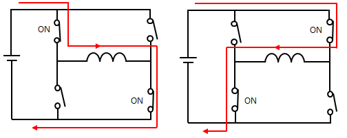
The circuit diagram is below. A circuit that combines four transistors like this is called an H-bridge circuit or a full-bridge circuit.
By turning on two transistors as shown below, the direction of the current can be changed.
This is the basic principle of generating alternating current. However, it is not possible to generate a sine wave simply by turning it on and off, so it is possible by attaching a coil that functions as a low-pass filter and switching on and off at high speed.
(reference:Sine wave generation method) ■Three-phase AC circuit using an inverterThe circuit that creates three-phase alternating current from direct current is shown below (switch descriptions are simplified, but they are equivalent to the switches above). The direction of the current changes depending on the state of the switch, but as a precaution, do not connect all three switches to the upper side.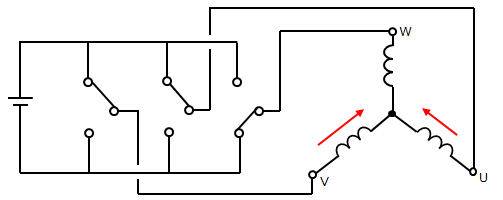
|
|
|||||